LP5562 I2C LED Driver for Particle devices
There are several possibilities for indicator RGB LEDs:
- Direct connection to PWM outputs
- Serial LEDs like NeoPixels (WS2812)
- I2C LED drivers
Direct PWM is the least expensive, but when you are using RGB LEDs you'll quickly run out of available PWM channels. You're pretty much limited to one additional RGB LED on most devices.
NeoPixels are a great option as you can string together dozens of LEDs off a single GPIO. There are a few downsides:
- You need to have 3.6V or higher. You can't run them off 3.3V.
- The NeoPixel library runs for long periods of time with interrupts disabled for long strands, which may affect performance of other code.
The third option is to use an I2C LED driver. That's what this library is for. It allows the use of the TI LP5562 I2C LED driver from a Particle device. Why it this useful?
- It runs at 3.3V
- Uses cheap off-the-shelf RGB LEDs
- You can include up to 4 of them on the I2C bus
- It can drive LEDs up to 25.5 mA, great for large indicator LEDs
- It has a programmable constant current driver so you don't need current limiting resistors
- It's a programmable smart controller so many LED patterns can be made without intervention from the MCU
What's the downside? It does add a chip ($1.14 in single quantities). The biggest challenge is that it's only available in a DSBGA12 package. This is a really, really tiny 3x4 BGA (ball grid array) chip. 1.648 mm x 1.248 mm. It's barely larger than an 0805 resistor, but with 12 pins. It can only be reflowed; it's obviously not possible to solder with a soldering iron.
On the plus side, you can put one of these on your board and it takes up less space than 3x 0603 current limiting resistors.
While it's designed to drive an RGB LED plus one extra LED (white), it actually can drive any four independent LEDs. There are a couple benefits of using "indicator mode":
- You can drive 4x LEDs up to 25.5 mA
- Only uses I2C, no GPIO
- Full programmable to be on/dim/off, plus programmable patterns like blink or breathe
The library
Using the LP5562-RK library is just a matter of adding the library to your project and initializing it:
You normally allocate the object as a global object:
In setup(), initialize the object. There are some options that you configure fluent-style then call the begin() method:
There are methods to set a constant color, blink, alternating blink, and breathe. This call does cyan breathing:
The options left to right are:
- red (disabled)
- green (enabled)
- blue (enabled) (green + blue = cyan)
- 20 the number of half milliseconds per step (10 milliseconds)
- 0 starting brightness
- 255 ending brightness
Full browsable API docs are available. The calls are extensively documented in the .h file. There's also a copy of the HTML docs in the docs subdirectory.
The three example programs illustrate all of the features.
I2C addressing
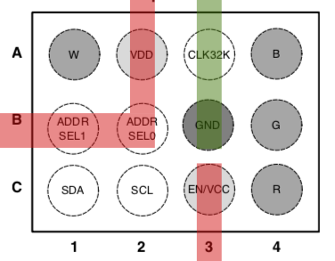
The LP5562 has two address select lines to allow you to connect four to a single I2C bus, using address 0x30 to 0x33.
Because of the closeness of the BGA balls if you use the external clock you'll probably be limited to using the single I2C address 0x30. The reason is that you'll probably need to route ground through pins B1 (AD1), B2 (AD0), to B3 (GND).
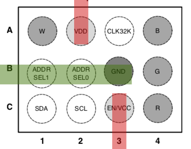
If you're not using an external clock and using the same power supply for VCC and VDD, then life is much easier, and all addresses are easily routed:
Address 0 (AD1 = 0, AD0 = 0, 0x30):
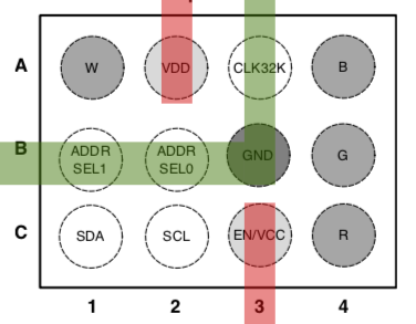
Address 1 (AD1 = 0, AD0 = 1, 0x31):
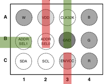
Address 2 (AD1 = 1, AD0 = 0, 0x32):
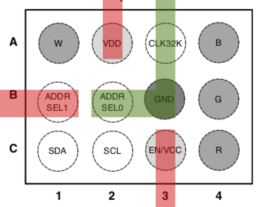
Address 3 (AD1 = 1, AD0 = 1, 0x33):
RGB Demo Board
I made a simple demo board to test and illustrate the use of the chip.
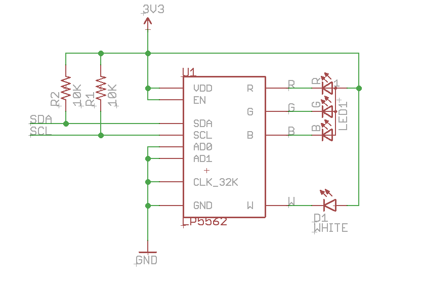
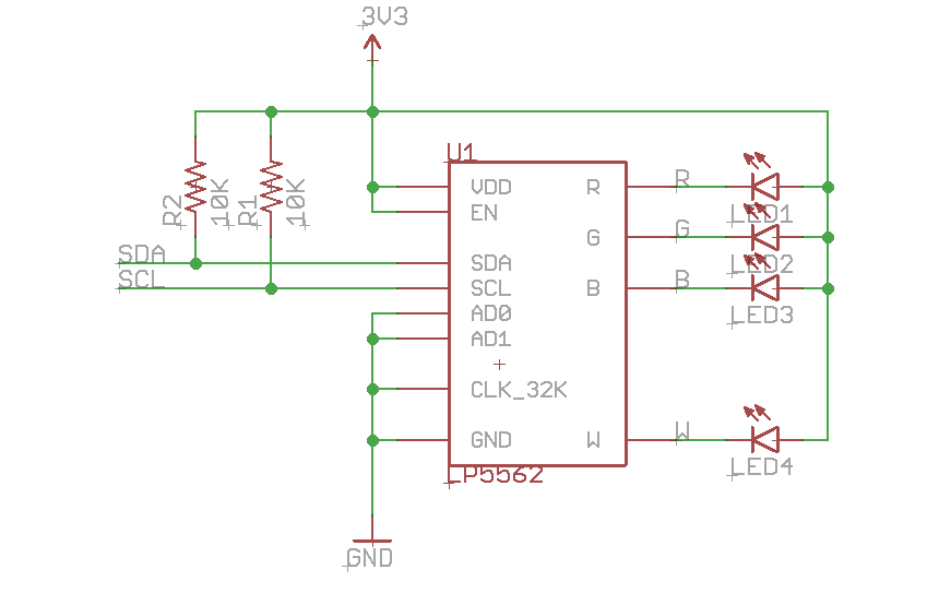
Here's the schematic.
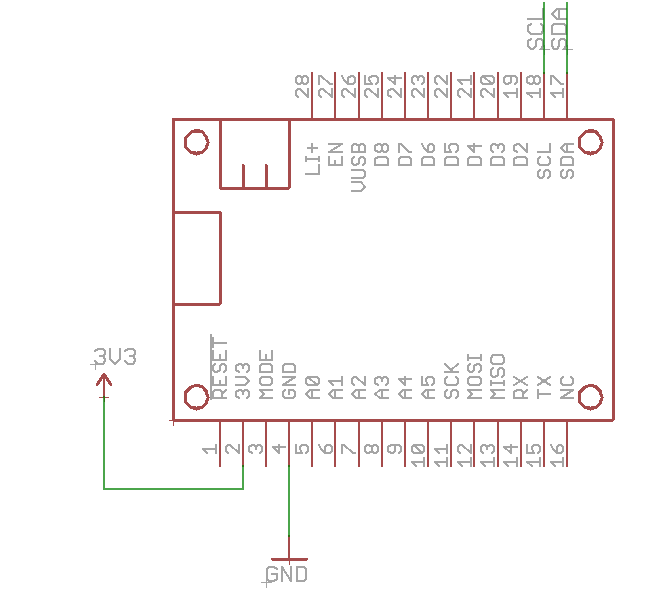
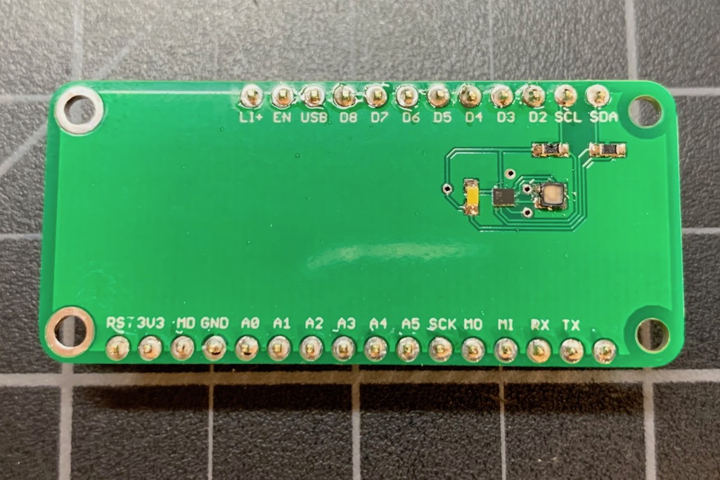
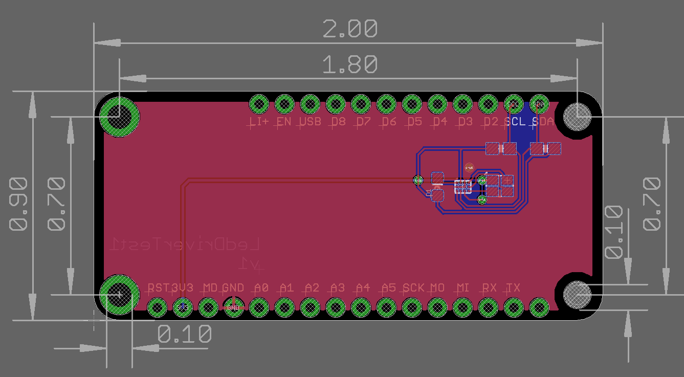
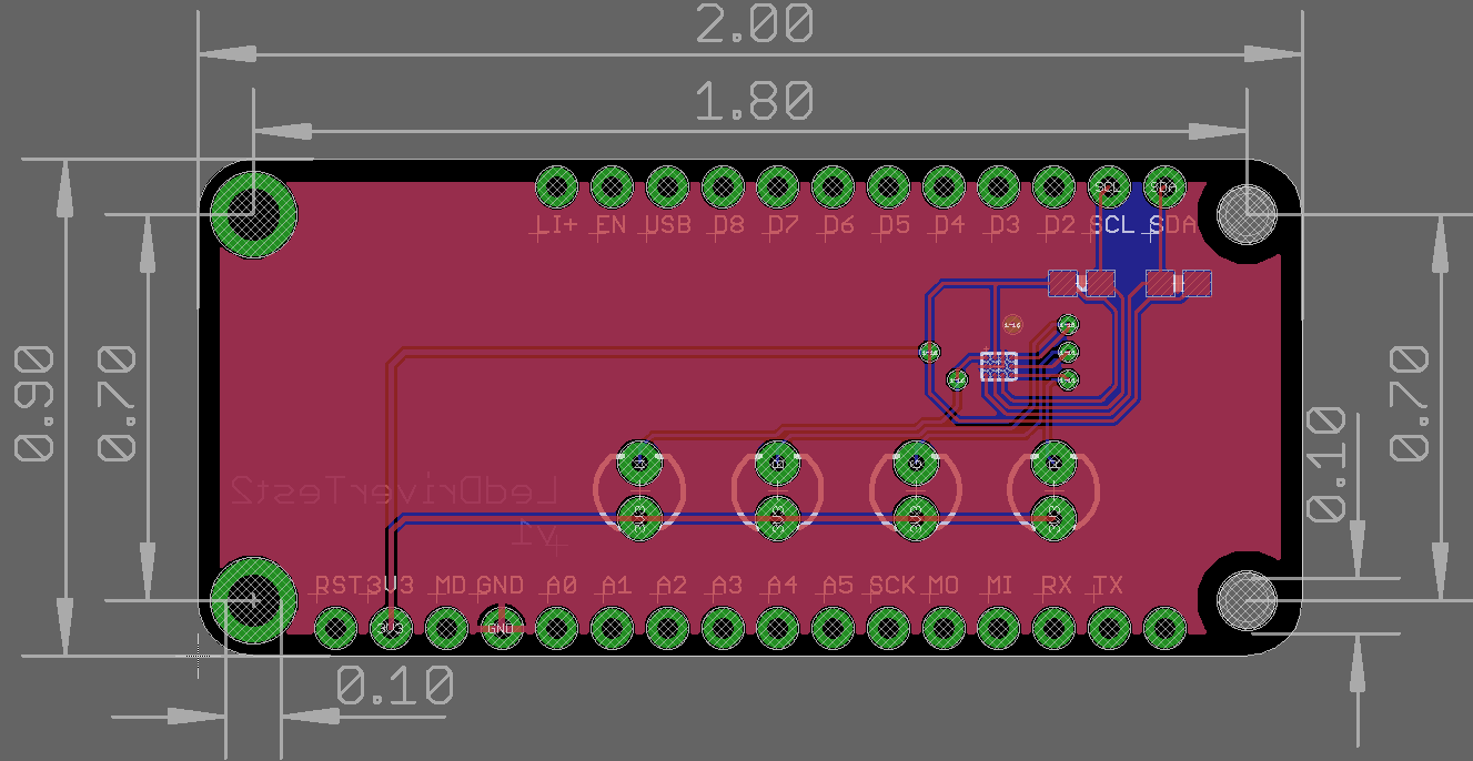
And the board. It's an Adafruit Feather form-factor, intended to be used in a double or tripler with a Gen 3 Particle device (Argon, Boron, or Xenon). Male header pins go on the bottom side.
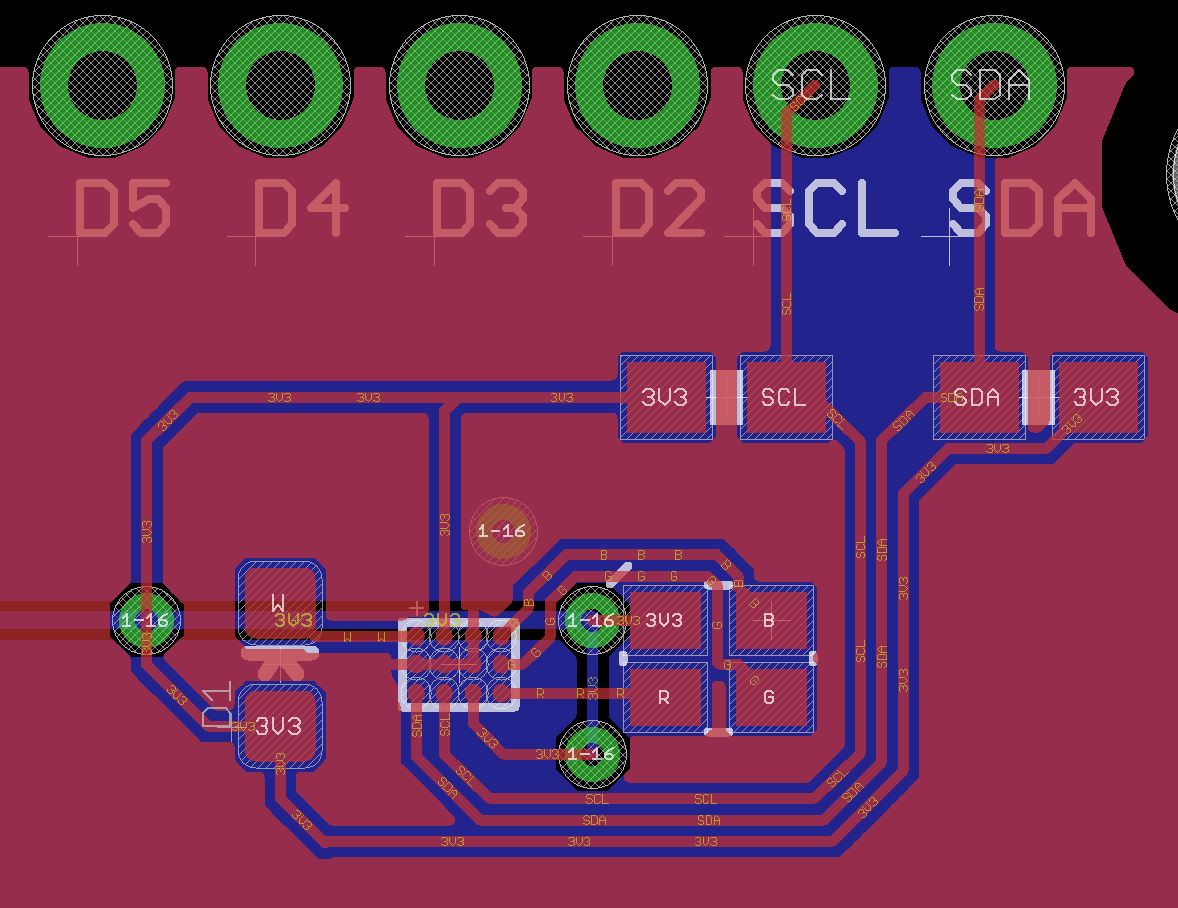
Close-up of the LED circuitry:
The eagle subdirectory contains the open source design:
- LedDriverTest1.sch (schematic)
- LedDriverTest1.brd (board layout)
- LedDriverTest1v1.zip (gerbers)
- LedDriverTest1.lbr (library with all of the components used on the board)
| Quantity | Item | Examp | |
|---|---|---|---|
| 1 | LP5562 | LP5562TMX/NOPB | $1.14 |
| 1 | RGB LED | Cree CLMVC-FKA-CL1D1L71BB7C3C3 | $0.19 |
| 1 | White LED | Lite-On Inc. LTW-C191DS5 | $0.55 |
| 2 | 10K Resistor 0603 | Panasonic ERJ-PA3J103V | $0.10 |
| Male header pins 0.1" </td> <td class="markdownTableBodyNone"> [Sullins PRPC040SAAN-RC](https://www.digikey.com/product-detail/en/PRPC040SAAN-RC/S1011EC-40-ND/2775214) </td> <td class="markdownTableBodyRight"> | |||
Indicator Demo Board
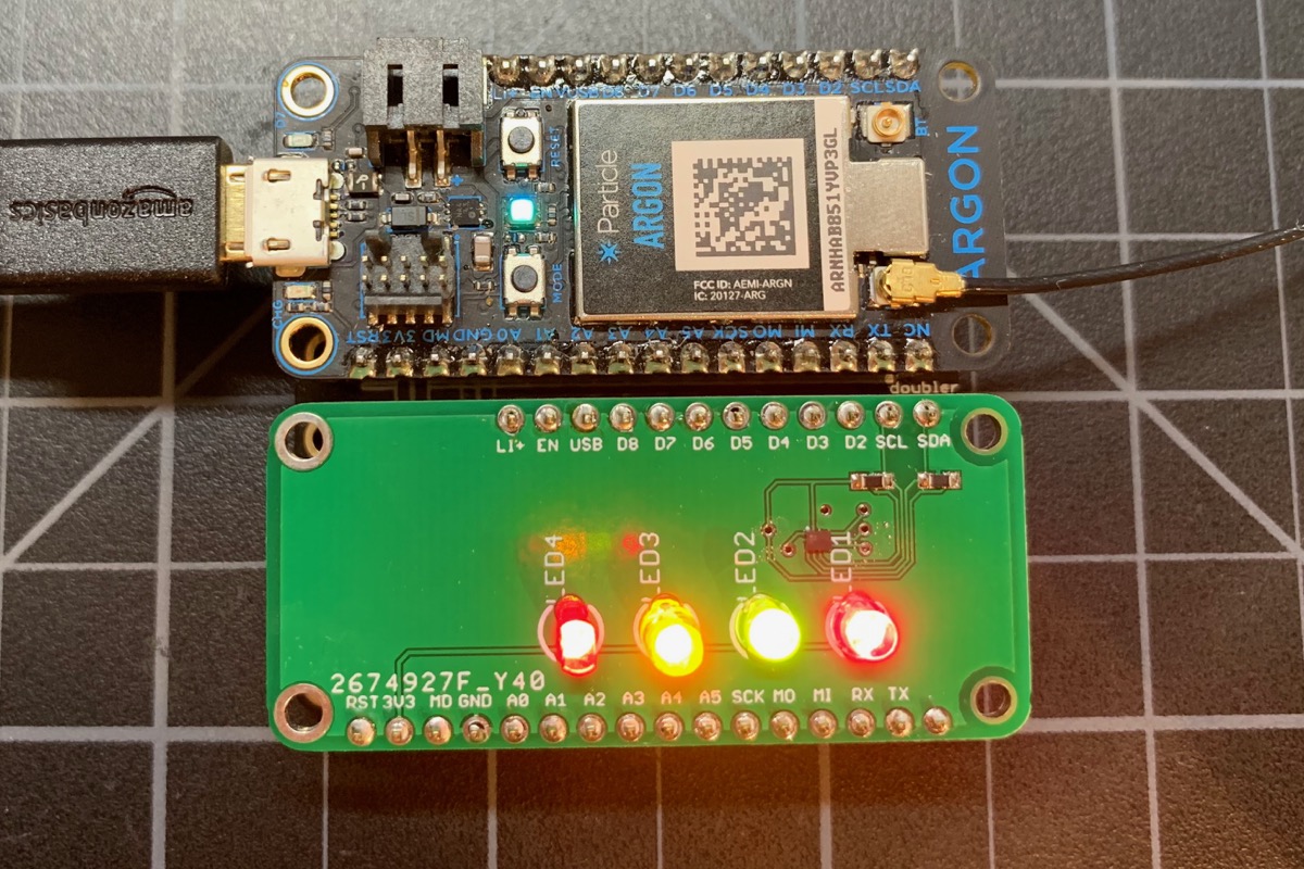
This demo board tests 4 discrete LEDs instead of using an RGB LED. I made it using T-1 (3mm) through hole LEDs because I had a kit of them so I could use 3 20mA LEDs and 1 10mA LEDs.
Schematic:
Board:
The main difference between indicator mode and RGB mode is how the engines are set up. Because there are four LEDs and 3 engines, indicator mode sets up the three engines with common patterns:
- Blink
- Fast blink
- Breathe
Then you can assign any LED to be on, dim, off, or one of the three available patterns. This provides a lot of flexibility given the hardware limitations of the LP5562. Of course the full LP5562 programming API is available as well if you want to go crazy with the customization.
If you are using LEDs with different current requirements you can use the withLEDCurrent() overload with separate settings for red, green, blue, and white.
To use indicator mode, use setIndicatorMode().
To set an LED, use one of the setLedMapping methods:
LP5562::REG_LED_MAP_DIRECTsets a direct PWM value. 0 is off, 255 is full brightness, and values in between are dimmed.LP5562::REG_LED_MAP_ENGINE_1is a normal blink.LP5562::REG_LED_MAP_ENGINE_2is a fast blink.LP5562::REG_LED_MAP_ENGINE_3is breathing.