Particle library for MCP79410 real-time clock (RTC) chip with I2C interface
Hardware
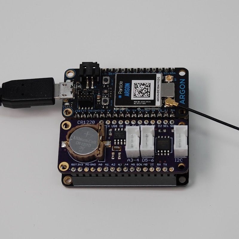
This is a sample board that includes an MCP79410 in an Adafruit FeatherWing form-factor. The documentation and Eagle CAD files for this project can be found here.
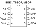
The MCP79410 is a tiny 8-pin chip:
With a simple application circuit:
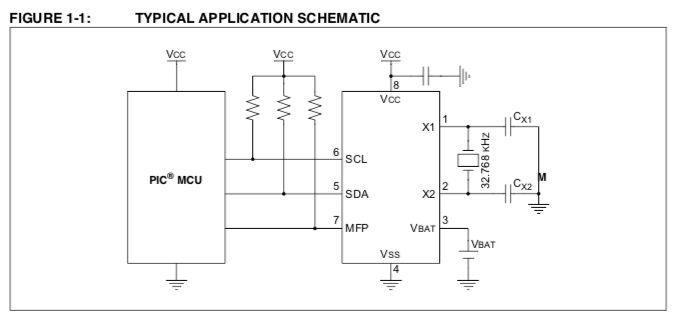
You only need some pull-up resistors, a 32.768 kHz crystal, and a few capacitors.
It connects by I2C and uses addresses 0x6f (registers and SRAM) and 0x57 (EEPROM).
The MFP pull-up
The MFP (multi-function pin) is useful when waking up from SLEEP_MODE_DEEP based on time on Gen 3 devices (Argon, Boron, Xenon). You connect MFP to D8 for this purpose.
However, you must be careful: Using D8 as a wake-up pin is active high, rising. The MFP is open-collector and requires a pull-up.
However, in SLEEP_MODE_DEEP, an internal pull-down (about 13K) is applied to D8 so it doesn't float if not connected. Thus you must use a small-resistance pull-up or the signal won't go high enough because of the conflicting pull-up and pull-down.
A 2.2K pull-up works fine for this purpose.
Or you could use an actual inverter or transistor, if you prefer.
If you use a typical 10K pull-up on MFP, in wake the signal will only reach 1.9V because of the 10K pull-up and the 13K internal pull-down, and that's too low of a voltage to register as high and end sleep mode.
Common Patterns
RTC Clock Synchronization
By default, bi-directional clock synchronization is done.
- During setup() if Time is not valid but the RTC is, then Time is set from RTC. This is useful because Time is not maintained in SLEEP_MODE_DEEP.
- During loop(), after Time is synchronized with the cloud, the RTC is updated. This only happens once at boot.
You must call the setup() and loop() methods, as shown in the following example.
Using RTC to wake from SLEEP_MODE_DEEP
Here's a simple program to wake from SLEEP_MODE_DEEP:
For Gen 2 devices, you might do something like:
but using the RTC it would be:
The reason for the error check around setAlarm is that the alarm can only be set after the RTC has been set to the correct time. Upon cold boot (no 3V3, no battery) the RTC won't be set and sleep cannot be used until the first clock synchronization. This is true even when delaying by seconds.
You can also use rtc.isRTCValid() to determine if the RTC is believed to be correct. If isRTCValid() returns true, then setAlarm() will typically return true as well. This is handy if you want to preflight setAlarm() before turning off the network connection, for example.
Using SRAM
The MCP79410 contains 64 bytes of battery-backed SRAM. This is handy if you want to store data data. This can be written to quickly and does not wear out. The data is preserved by the backup battery (CR1220 in the design above) when there is no power on 3V3.
The API works like the EEPROM API in Device OS:
The first parameter is 0, and that is a byte offset. Make sure you leave enough room! The next data should be written at 4, leaving enough room to save the 4-byte (32-bit) integer.
You can get and put simple data bytes (int, bool, uint32_t, etc.) and struct.
Note that you cannot put a String variable or char *! You need to set aside enough bytes and copy the string to the bytes.
Using EEPROM
The MCP79410 contains 128 bytes of byte-writable EEPROM. This is slower to write to, but the data is preserved forever, even with no battery. The EEPROM can also wear out; it's rated for 1 million erase-write cycles for each byte.
The API works like the EEPROM API in Device OS:
Using the Protected EEPROM Block
In addition to the 128 bytes of EEPROM, there's a special block of 8 additional bytes of EEPROM. This is harder to access and accidentally erase.
This is often used for things like MAC addresses, however I think it would be perfect for storing board revision and capability information.
The 7-board-id-set example shows how to store data in the protected EEPROM.
The 8-board-id example shows how to read it: